ExAC Section 3 Sample Exam — 5 Free Questions

Issued for Interns
All Samples Get the Guide
← All Samples

Section 3 focuses on construction principles, materials, building science, construction processes, and project specifications. It maps to Themes 7, 8, and portions of Theme 12 in the ExAC blueprint. The full exam has 120 multiple-choice questions over three hours. Topics span building envelope detailing, moisture and vapour management, structural connections, concrete, masonry, wood-frame and steel construction, roofing assemblies, and the preparation and interpretation of project specifications. Questions often require you to identify construction errors, evaluate material substitutions, or apply knowledge of Canadian industry standards to a described scenario.

These five sample questions are drawn directly from the Issued for Interns question bank and reflect the technical depth expected in the full Section 3 exam. This section rewards candidates who have real-world construction experience or who have deliberately studied building assemblies at the detail level required by a practising architect. Each question is followed by a full explanation covering the underlying principles and the correct reasoning. The complete study guide includes comprehensive notes on every Section 3 topic, 500+ practice questions, and full-length timed mock exams for Canadian intern architects preparing for the ExAC.

Pay attention to the detail-level reasoning in each explanation; Section 3 rewards candidates who understand assemblies, not just terminology. Every question in this sample is written and reviewed by licensed Canadian architects to give you a sense of what you will face on exam day.

Loading sample questions…
Section 3 sample questions & answer explanations

Here are all five Section 3 sample questions in full. Read each question, choose your answer, then expand the explanation to see the correct choice and the reasoning behind it — the same detailed rationale included with every question in the full study guide.

  1. Question 1Theme 8

    The four wall section diagrams shown each depict a steel stud exterior wall assembly for a cold Canadian climate. Which section correctly locates the vapour retarder and insulation layers?
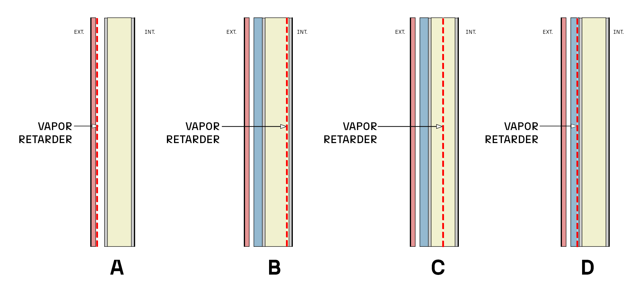
    Four steel stud wall section diagrams labelled A–D, each showing a different placement of vapour retarder and insulation layers for a cold-climate exterior wall assembly.
    • ASection A — vapour retarder on the inside face exterior cladding with cavity insulation only
    • BSection B — vapour retarder on the interior (warm-in-winter) face, continuous rigid insulation on the exterior of the stud, and batt insulation in the cavity
    • CSection C — vapour retarder in the centre of the cavity, splitting the insulation layer in two
    • DSection D — vapour retarder between rigid insulation and exterior sheathing
    Show answer & explanation

    Correct answer: B

    In a cold climate, the vapour retarder must be placed on the warm-in-winter side — at the interior face of the stud cavity, behind the gypsum board — to prevent moisture-laden interior air from diffusing into the colder portions of the assembly and condensing. Continuous rigid insulation on the exterior of the stud eliminates thermal bridging through the metal and keeps the sheathing and air/weather barrier warmer, further reducing condensation risk. Placing the vapour retarder on the exterior (cold) side reverses the correct physics and guarantees interstitial condensation within the assembly.

  2. Question 2Theme 8

    The parapet detail shown is described by Lstiburek (Building Science Corporation) as a "Problem Parapet — everything is wrong." Which of the following best summarises the combined enclosure failures illustrated?
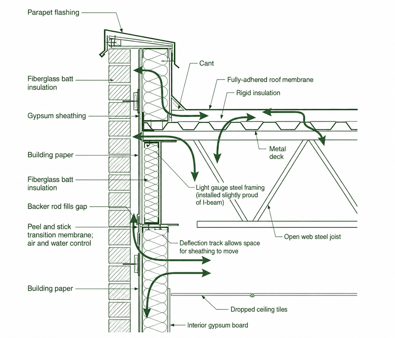
    Building Science Corporation Figure 6 — Problem Parapet. A vertical section through a parapet and roof-wall junction showing blue arrows indicating air leakage paths into and out of the assembly in multiple locations. Labels identify: parapet flashing with no membrane beneath it, fiberglass batt insulation, gypsum sheathing, building paper, peel-and-stick transition membrane at a lower level, fully-adhered roof membrane, rigid insulation, metal deck, light gauge steel framing, open web steel joist, and interior gypsum board.
    • AThe parapet is too short, the coping is missing, and the roof slope is insufficient to drain toward the interior drain
    • BThere is no continuous air control layer in either the roof or the wall assembly, no membrane under the parapet flashing to connect the roof and wall control layers, no vapour control layer, and thermal bridging occurs throughout — allowing air leakage into and out of the assembly at multiple locations
    • CThe rigid insulation is installed above the membrane rather than below it, inverting the roof assembly into an unintended PMR configuration
    • DThe steel framing conducts heat through the assembly, but the air and vapour control layers are correctly located and continuous across the roof-wall transition
    Show answer & explanation

    Correct answer: B

    Lstiburek identifies this parapet as failing on every enclosure front simultaneously: (1) no membrane under the parapet flashing means the roof and wall rain/air control layers are never connected at the transition — the most critical joint in the enclosure; (2) there is no continuous air control layer in either the wall or roof assembly, so air (and the moisture it carries) leaks freely in and out everywhere; (3) there is no vapour control layer; and (4) thermal bridging occurs throughout the steel framing. The blue arrows in the diagram trace the air leakage paths that result. A correct parapet connects the roof membrane continuously to the wall air/weather barrier and maintains thermal and vapour control across the transition.

  3. Question 3Theme 8

    In the roof framing diagram shown, the sloping line running from the ridge down to an exterior corner where two roof planes meet at an inside angle is labelled element X. Element X is a:
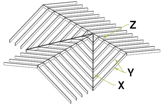
    Roof framing plan or perspective of a hip-and-valley roof. Element X labels the sloping rafter at an inside corner (valley) where two roof planes meet. Element Y labels the sloping rafter at an outside corner (hip) for contrast. The ridge board, common rafters, and a jack rafter are also visible.
    • AHip rafter — the sloping rafter at an outside corner where two roof planes meet
    • BValley rafter — the sloping rafter at an inside corner where two roof planes meet, channelling rainwater down to the eaves
    • CJack rafter — a shortened rafter running parallel to common rafters and framing into a hip or valley
    • DRidge board — the horizontal member running along the apex of the roof
    Show answer & explanation

    Correct answer: B

    A valley is the inside corner formed where two sloping roof planes intersect. The valley rafter runs along this line from the ridge down to the eave, and a valley flashing (sheet metal or pre-formed membrane) is installed over it to collect and direct rainwater away from the joint — making the valley one of the most water-vulnerable locations on a sloped roof. A hip is the outside corner equivalent where two planes meet at a projecting corner; jack rafters frame perpendicular to hips and valleys; the ridge board runs horizontally at the apex.

  4. Question 4Theme 8

    Which set of documents, issued for permit and construction, is considered the definitive description of the project for contractor pricing and execution?

    • ADesign development drawings
    • BConstruction documents (working drawings and specifications)
    • CSchematic design drawings
    • DAs-built drawings
    Show answer & explanation

    Correct answer: B

    Construction documents (CDs) — the final working drawings and specifications — define the scope, quality, and quantity of work with sufficient detail for building permit submission, contractor pricing, and construction. DD drawings are preliminary; schematic drawings are conceptual; as-builts record the finished condition.

  5. Question 5Theme 8

    In a set of construction documents, which drawing type establishes the overall dimensions, geometry, and spatial layout of the building on its site?

    • ASection drawings
    • BDetail drawings
    • CSite plan
    • DReflected ceiling plan
    Show answer & explanation

    Correct answer: C

    The site plan shows the building footprint on the property, setbacks, grades, access, utilities, and north arrow. It is used for zoning review and locating the building on the site. Section drawings show interior vertical cuts; detail drawings show construction assemblies; RCPs show ceiling information.